Installing an ATX Power Supply into a TI-99 PEB
Right off the bat, let me say
that this was a bad idea. I failed to sufficiently plan the project. But I'll write it up below as if I really
DID plan it out. However, don't expect full instructions or a step-by-step guide. If you are clever enough to
recognize the reason it's a bad idea, you should be able to work out how it goes together.
The TI PEB power supply is HEAVY. It's OLD. It's WEAK. I thought, hey, what the heck, let's replace it with a
nice 250 watt power supply, and look! Hey! I happen to have one! And so off I went.
I used an ATX power supply, although an AT power supply would be a little easier. Essentially I started by
removing the two hundred and seventy-five thousand screws that TI used to hold the PEB together, and the 4 screws
that held my ATX power supply together.
On the PEB side, I then removed everything - the transformer, the fan, the power supply, the switch and the
cables. The power supply board was mounted on a nice plastic upright mount - I removed it, and mounted the ATX
power supply board there. This took a bit of creativity, which will differ for your supply, no doubt. Just be
safe, whatever solution you come by. Remember that you're playing with electricity.
I ended up keeping the original switch - it suited my needs well. I discarded the ATX main power switch,
deciding it would just sit in stand by mode all the time. Pin 14, when grounded, instructs the power supply to
turn on. So, I ran the switch between pins 14 and 15.
Next came the fan - happily, the fan mount in the PEB is the right size for a standard PC case fan, which is
what I installed.
I mounted the power supply board a bit further inside the case than it was originally mounted - knocking out
one of the transformer mounts to make it fit. This was just a quick solution to spacing being a little different
than on the original board, and there's lots of room to do it.
Finally, time to hook up the power supply to the backplane board. On the ATX power supply, pin 10 (yellow) is
+12v, and pin 12 (blue) is -12v. The rest are not needed.
Matching this on the TI, black is ground, green is +8v, red is +16v, and yellow is -16v.
So, all we do is match them up and.... uhoh.
Well, now you see the problem that failing to plan ahead brought me. An ATX supply doesn't provide enough
voltage. TI specified that all cards would provide their own voltage regulation to 12 and 5 volts - the voltage
drop (roughly 3v) starting at 12 and 5 volts just won't do.
All right, fine. It was too late to go back now. My decision - bypass the voltage regulators on all the
cards. After all, the voltage is now regulated by this nice switched mode power supply. And this does work. But
it's a pretty dumb thing to have to do. It means you may fry your cards if you ever plug them into an unmodified
PEB.
Tim Tesch, some time ago apparently, posted a suggestion which was forwarded to me. Instead of bypassing the
regulators, simply wire the ATX +12v to *both* the TI +16v and +8v lines. The card regulators will take the 12v
down the 5v quite well, and the drop on the 12v lines is still good enough to run the card. (Also wire the -12v
to the PEB's -16v line). (He tested on RS232 and HDFC, I'm testing on the TI 32k and Disk, and Corcomp RS232).
This does in fact work and is a much! better solution. So if you want to try it - do that.
Here are my pics:

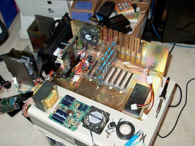
Top view of the modified PEB. You can see the new fan is a Penguin Cooler fan, the
switched mode supply sitting roughly where the transformer used to be, the backplane and the memory expansion
card plugged into it (sans shell). Note that I needed an extension for the disk drive power cable to reach all
the way to the floppy bay. You can see, in front of the case, the old fan, power supply board, and transformer.
(The fan and transformer weigh nearly 5 pounds combined.. they're heavy!)

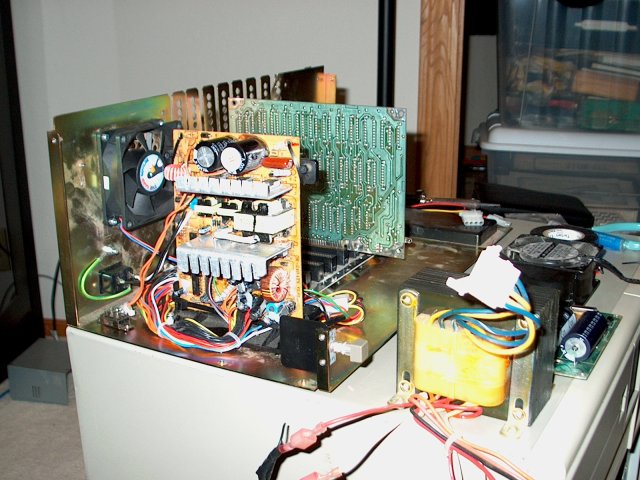
Side view, closer look at the switched mode board, which alone is nearly smaller
than the transformer. The small switch on the floor of the PEB, left corner, is the 110v/220v switch. It's not
exposed to the outside, I just needed somewhere to stick it. But there's no reason it couldn't be used.

BIG time thanks to Thierry Nouspikel for his TI Tech Pages, and for answering
a stupid question about the regulator in the end of the cable that I really should have known.
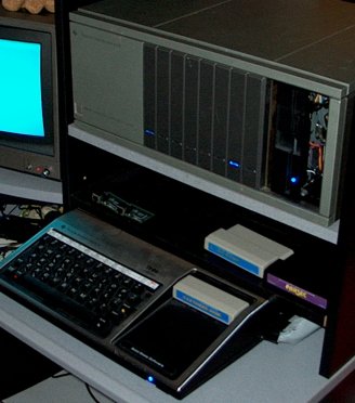
While I was in there, I also replaced the LEDs with blue ones. ;) It looks cool...
This page belongs to  , taking technology where it doesn't belong!
Click here for the main page


 , taking technology where it doesn't belong!